VVA with roller
Intellectual Property: patent EP 1,697,619
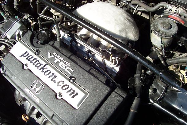
Inside the cylinder head of this Honda Civic B16A2 engine, photo below, is the "pattakon VVA Roller Version".
It controls all valves, intake and exhaust.
The valve lift is continuously variable from zero to 12mm.
Rev limiter at 9,000 rpm, flat torque curve and smooth idling at 330rpm.
Instead of throtle valve, it has a true "free flow" / "zero cost" ITB.
Click on the photo for a brief presentation on how it operates.
VVA Roller Compared To Existing
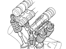
You can hardly find articles (on the web, in magazines etc) where the writer doesn't praise the engines of Honda S2000 and Honda Civic TypeR (above left) as the best ever: economic, environment friendly, extraordinary powerful and at the same time driver friendly.
What makes the difference is simply their two modes of operation (or of breathing), one for high revs and another for medium to low revs. To achieve the two step operation they use, per pair of valves, three cam lobes, three rocker arms, three rollers, some locking pins and hydraulic control. The rocker arms are made with extreme construction accuracy, and every time the lift is changed the system ought to pass through a "critical condition": it is the moment the rockers ARE and ARE NOT engaged (the "critical condition" is also met in Toyota's GTS/VVTLi, in Porsche's VarioCamPlus etc : every time the lift is changed some pins or wedges and their holders are "punished" and have to endure the abuse).
Throw away the two side cam lobes (get rid of them or just keep them idle).
Throw away one of the two "side" rollers and use the other one as the "free" roller cam follower.
Throw away the locking pins.
Throw away the hydraulic control system, or short circuit it.
Rotate properly the central rocker and weld (glue/paste/union) the three rocker arms to form a single one having a single roller (or substitute the three rocker arms with a single piece light alloy one).
Insert the "free" roller between the wild cam lobe and the roller on the rocker arm.
Insert a "slowly moving" almost idle control shaft, on which rolls the pin of the "free" roller.
And forget "critical conditions" and extreme accuracies, because now the transition from one mode of operation to another occurs smoothly / progressively / softly, by just rotating the control shaft easily, as your foot presses the gas pedal (no pins and holders, no ON-OFF operation).
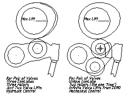
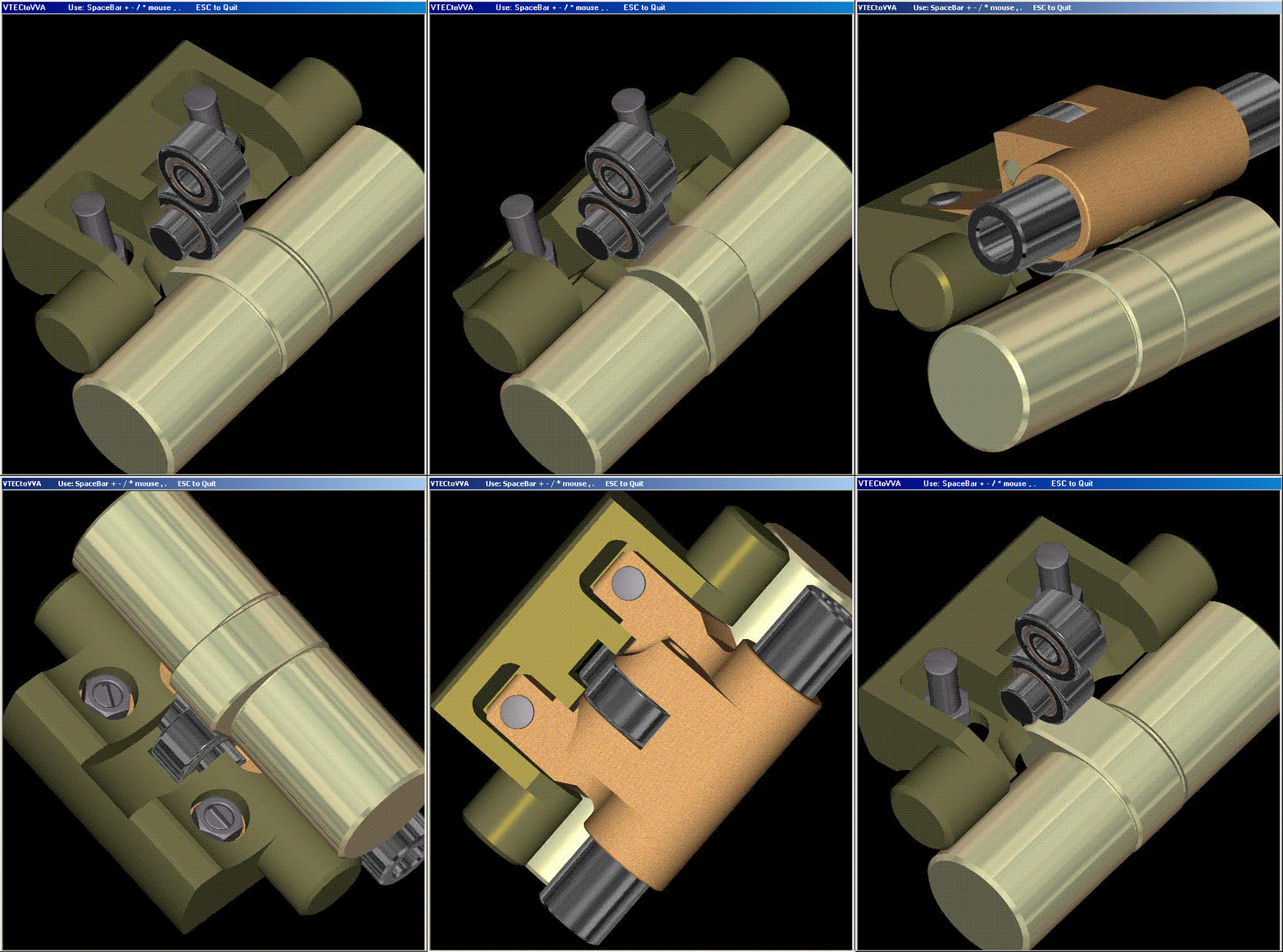
The 2D animation above explains things (mouse click on the picture to download the file, and then open it):
The mechanism at the left side of the animation is the existing one, the state of the art, while the mechanism at the right side is the new one. For simplicity it is shown, in the mechanism at left, only one of the side rocker arms. When the animation is running on the screen, press Space Bar key on keyboard to get the next available mode. Use the , . / keys of keyboard to proceed step by step.
The mechanism at left has just two modes of operation: 11.0 mm or 7.7 mm valve lift. When the wild cam lobe activates the valves, their stroke is 11.0 mm and when the mild cam lobes activate the valves their stroke is 7.7 mm and their duration shorter. The mechanism at the right side has infinite (limitless) modes, of which only four are shown, for 12.3, 7.5, 4.0 and 1.6 mm valve lift. At low revs and partial loads (i.e. at short valve lifts) the actual overlap of the mechanism at the right side is many times smaller than the overlap of the original engine, therefore it is as wrong as it gets that the new mechanism does not control overlap as well. On the contrary, the new mechanism is a very effective Variable Valve Timing (or "actual overlap control") system: starting with strong overlap and cam lobes of long duration and of high lift, the dramatic reduction of the valve lift at medium, low and extremely low revs drastically and effectively reduces, or roughly eliminates, the actual overlap. All it takes, to change the valve lift, is to rotate the control shaft by pressing the gas pedal with your foot. The operation is continuous (and not ON-OFF). The intake manifold and its throttle valve can be eliminated as the intake valves can play the role of the throttle valve too.
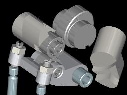
In the 3D animation the control shaft is sliced to expose the parts of the mechanism beneath. The one piece is in its normal place and the other one is shown at the right side of the window. The "free" roller cam follower rolls on the cam lobe periphery and on the rocker arm roller periphery and not on the control shaft. Only the pin of the "free" roller rolls along a cylindrical surface cut on the control shaft and shown in the right side. The other two cylindrical surfaces (or slices) on the control shaft are there to make space for the motion of the free roller and of the cam lobe.
The control shaft is well oversized and heavier than necessary only to emphasize that there is plenty of space for its installation into any engine already in the road.
The pin of the roller of the rocker arm can be held on the rocker arm even without complete "rings", like the fork in the animation "VVAFreeRollerRockerFork", as the direction of the load is limited.
If necessary, practice proves unnecessary so far, a spring from the body of the rocker arm to the pin of the free roller can provide the necessary restoring force at low or zero valve lift, in order to keep the free roller in touch to the cam lobe.
The result?
Infinite modes of operation with valve lifts varying from about 0.2 mm (for idling) to more than 12.0 mm (compared to just 11.0 mm or 7.7 mm of the original engine), excellent control of the actual overlap and ability of using any combination of exhaust and intake valve lifts (i.e. 12.0 mm exhaust with 1.0 mm intake, but also 0.7 mm exhaust and 1.0 mm intake etc).
And what is so important from the drivers/neighbors/citizens point of view?
Significantly less fuel consumption and pollution at idling, at low revs and at partial loads: it is the town traffic itself.
Less consumption and pollution at all revs and loads.
Smoother idling at lower revs and easier starting at all conditions.
Capability for higher revs as concerns the limitations imposed by the valve train system, due to the lower inertia of the quickly moving parts.
Longer time intervals between valve train adjustments, because most of the time the valve train system operates almost without loads. It is obvious that at partial lifts the stress in the valve train is incomparably smaller as opposed to the conventional or the two step mechanisms.
More power output, because the peak torque of the original engine can now be sustained beyond the red line revs, without any spoiling of the drivability at medium and low revs or at lighter loads: on the contrary at low to very low revs the engine becomes very torquie.
Freedom to choose throttless operation.
Freedom to use cheap "throttle bodies" (without throttles inside, i.e. "throttless throttle bodies", as the throttling is now the job of the intake valves, which have continuously variable lift, from zero) in the place of the existing intake manifold.
By selecting just two valve lifts or control shaft angles, from the limitless available, the engine with the new VVA is reduced to the state of the art VVA engines, that is it can operate similarly to the existing engines with the only two modes of operation, like Honda S2000, Honda Civic TypeR, Toyota VVTLi/GTS, Porsche Variocam Plus etc. The rest infinite modes are there to prove the superiority of the new system and to improve spherically the behavior of the engine at all revs and every load, offering the option to choose the best - from infinite available - mode of breathing for the specific operational conditions.
Two step compared to continuously variable breathing systems: it is like having a shoe-shop offering just two sizes of shoes, one for children and one for adults. If the customer is lucky OK, if not... The example seems extreme, but deeply looked it is a good one. Of course two step systems are better than conventional (only one size of shoes), but when all demands can be satisfied, why to compromise in just two lifts?
The reason for going from two or three step systems to continuously variable valve lift systems is exactly the same reason for going from conventional to two or three step systems: to improve the internal combustion engine. Above everything else to increase the intake air velocity, because the flame propagation is proportional to the air velocity. And as there is no substitute for a faster combustion, there is no substitute for the fast air motion during combustion. All the rest are details. Just look around to see the struggle to make the incoming air a little faster.
To summarize:
Starting with a Honda S2000 or a Honda Civic TypeR or a Toyota Celica GTS/VVTLi engine :
* the existing rocker arms are modified or replaced (the final ones are simpler, lighter and stronger),
* two control shafts are rotatably mounted along cylinder head beside camshafts,
* the EFI unit is reprogrammed,
and this is all. The original camshafts remain in their original bearings with their mild cam lobes inactive, the timing chain is the original at its original position, the external dimensions of the engine stay as they were, and so on.
Once again: fewer, lighter and simpler quick moving parts, easy control, continuous operation without "critical conditions" are only some of the benefits the new system can offer to the state of the art engines.
And as regards the reliability, suffices it to notice an obvious thing: since the new system will spend most of its life at partial loads and at medium to low revs (as all road engines do) it will last much longer than the rest parts of the internal combustion engine. As you can see, for the new system medium to low revs and partial loads (i.e. short valve lifts) mean operation practically without loads, and hence without wear or fatigue of the parts involved (i.e. reliable operation and longer time intervals between tuning/adjustments).
VVAFreeRollerFlatWallStereo
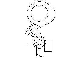
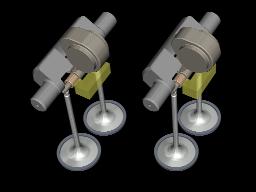
Here there is an immovable wall (the rectangle parallel to the valve axis). There is a valve roller on top of the valves. There is also a "free" roller cam follower. The free roller rolls on the cam lobe as the cam rotates. The "free" roller rolls also on the valve roller. The pin of the free roller rolls on a cylindrical surface of the control shaft. The control shaft is rotatable about the axis of the "free" roller when the later is at "rest" position, i.e. in contact to the basic circle of the cam lobe. The valves are free from thrust loads (just like in the case of bucket lifters). The mechanism is lighter and stronger and of lower friction. All working surfaces are rolling to each other and no one is sliding.
In case the radius of the cylindrical surface of the control shaft along which rolls the pin of the "free" roller equals to the sum of the radiuses of the valve roller, of the free roller and of the free roller pin, the system can offer zero valve lift too.
In case the free roller is removed and the camshaft acts immediately on the valve roller, a "constant" lift system results that can replace the conventional "bucket lifters" system, providing less inertia and less friction. It is the arrangement without control shaft, in the last image showing "various arrangements".
VVAFreeRoller&BucketLifters
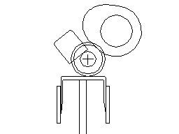
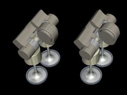
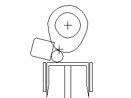
Here a "free" roller cam follower rolls on the cam lobe, on the upper surface of the bucket lifters, and along a flat surface of the control shaft. As the control shaft rotates, the valve lifts change from zero to a maximum. The system can work even if the triple roller shown is substituted with a single low diameter pin as shown in the "VVAFreePinFlatControl" animation above.
VVAFreeRoller&Rocker
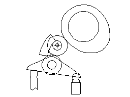
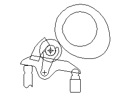
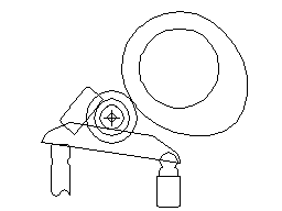
The mechanisms shown can easily be applied in engines with rocker arms / hydraulic valve clearance adjusters (very common arrangement lately).
Modifying the rocker arm, the original roller can be moved lower in order to make space for the insertion of the free roller without the need of displacing the camshaft.
There is the option to remove the rocker arm roller and replace it with a fork/holder of the free roller, as shown in the next animation.
There is also the option to flatten the upper part of the rocker arm and use just one roller and a flat surface on control shaft.
In case of mechanical lash adjuster, a coaxial to the adjuster spring can keep the lash of the mechanism only in the swivel joint.
VVAFreeRollersRockersUniCam
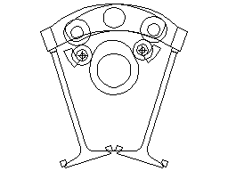
In case of engines with single camshaft and rocker arms, free rollers can be inserted between the rollers of the rocker arms and the cam lobes. The two control shafts can combine any valve lift in intake to any valve lift in exhaust. The system remains very short and simple. There is the option to use a unique cam lobe to control all cylinder valves.
VVAFreeRollers&Rockers&UniCam&CommonControl
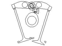
In case of engines with rocker arms, single camshaft and double pivot shafts, free rollers can be inserted between the rollers of the rocker arms and the cam lobes. In this case, a unique control shaft can control the intake and the exhaust valve lifts. The system remains very short and simple.
The Forums and the alternatives
The VVA system was published in more than 250 Internet Forums relative to engines, cars, motorcycles, racing, technology and ecology. The typical comment was : but the small "push rods" seem weak. Actually the small "push rods" are too strong and too light and their benefits are proved in practice. Nevertheless it is now published another version of the VVA system with rollers as the means for keeping the distance of specific axes constant. In the arrangements below the "control shaft" is red.
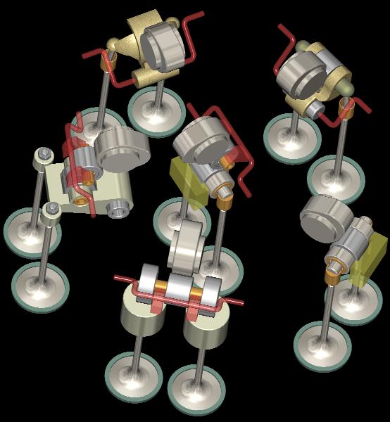
In some cases there were mentioned the hydraulic and the electromagnet alternative systems as a better solution. The main advantage of the hydraulic and electromagnet systems is their theoretical ability to control all the parameters, i.e. the duration and the lift and the timing. Theoretically they seem superior. But in practice there are still many problems to be answered. Let alone their power consumption.
The new VVA, in comparison, appears simple and carry all the experience of the camshaft based systems. Its energy consumption is not just beyond competitors, but literally speaking it is several times less than their best. It consumes very small amounts of power (friction) at short and very short valve lifts, i.e. where the normal engine spends almost all its life. It also provides infinite modes of operation and effective control of the overlap, without the need of additional timing system.
"But the hydraulic / electromagnet systems will offer absolute control", some people insist.
The case reminds someone found in the desert, thirsty to death, who refuses to drink the water offered to him because it is neither mineral nor of his favor brand. To evaluate cam-less systems, they have first to get in practice.
For the moment the new VVA seems the best solution as it combines:
the economy, the low pollution and the easy handling of BMW's valvetronic (which, on the other hand, is not applicable to exhaust valves, cannot efficiently handle the condition of low revs with full load, and cannot achieve high power concentration as it is unable to operate reliably at high revs),
with the high (or even higher) power concentration of Honda's S2000,
without the "critical conditions" of Honda's VTEC,
without the height, the stress and the wear concentration points of BMW's valvetronic,
with simple mechanical or electromechanical control ,
with low height, weight and friction,
with reliable operation,
and, above all, with the ability to be installed on new and old engines easily and at low cost.
In any case, the world must be grateful to BMW for valvetronic and to Honda for VTEC, because these two companies, among automakers, do improve for a step the "internal combustion engine". BMW claims - with valvetronic - a 10 to 15% fuel economy and pollution reduction, combined to improved drivability, and nobody doubts. And with S2000, Honda proves it is possible to get (milk) from an engine 120 PS per liter and at the same time good behavior at medium and low revs.
The new system does combine and improve the benefits of both schools, being at the same time simpler and cheaper.
On the other hand, the hybrid cars are based exclusively on the weakness of the car engines to have acceptable efficientcy at specific conditions (of revs and loads) frequently met in town traffic. But if the efficiency of the reciprocating engines becomes acceptably good along all the spectrum of loads and revs, then the hybrid car's position weakens. Just a system to stop and restart (turn off and on) the engine when the car waits in traffic lights, combined to the VVA system and to a long ratios gearbox (the plenty of torque from extremely low revs, due to the VVA, overcomes the long ratios), is all it takes.
Indicative Data Logs
Engine: Honda B16A2 (1600cc, 4-cylinder, 16 valve) with the pattakon VVAr on intake and exhaust valves (full version).
Data Logger: Hondata s200.
Open loop mode.
The log files A1MOV.PNG and A1MOV.pdf correspond to the following QuickTime video:
Click on the above image to download the 4MB video of the car accelerating on a public road (or click here for the youtube version).
This data logging is one of the first, with the engine still having the original valve springs on it.
The injection/ignition tables finish at 1 Bar.
The log files no70.PNG and no70.pdf is an indicative data logging.
A set of "egg shape" Toda valve springs are installed (they are harder than the original valve springs and allow more than 12mm valve lift).
The columns from B11 to B16 of Hondata�s system (typically used for turbo applications) are active in injection/ignition tables.
The no70Analysis.pdf is an analysis of the no70 data log. The blue curve is the lambda value times the injection duration value, i.e. it is the quantity, per cycle, of air that is handled by the engine. At a first approach the blue curve gives the form of the torque curve.
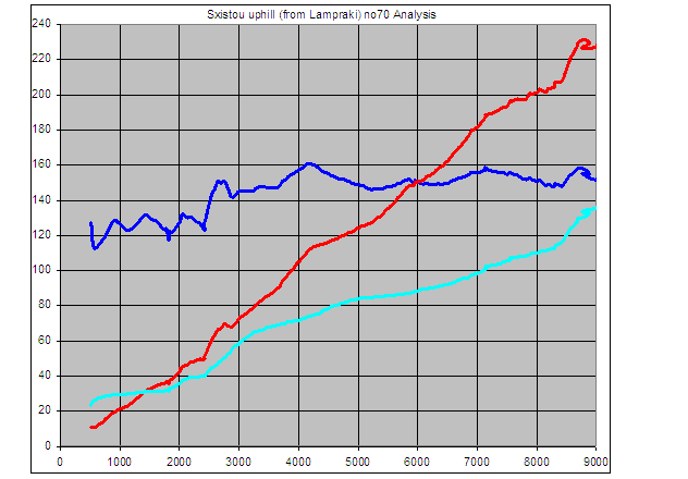
The red curve is the value of the blue curve times the revs (horizontal axis). Roughly speaking, the red curve gives the form of the power curve.
The cyan curve is the MAP sensor. It gives an idea of how much the gas pedal was pressed (i.e. of the valve lift) at the specific revs.
The log files ja21.PNG and ja21.pdf is another indicative data logging.
The car moves slowly with 3rd gear at a steep uphill road.
The ja21Analysis.pdf is an analysis of the ja21 data log. The blue curve is the lambda value times the injection duration. This curve simply says that the engine at 750 rpm can handle per cycle some 130 units of air quantity, while the same engine at medium and high revs can handle some 150 units of air quantity.
The red curve is the value of the blue curve times the revs.
The cyan curve is the MAP sensor. It gives an idea of how much the gas pedal was pressed at the specific revs.
The log files de96.PNG and de96.pdf is another indicative data logging.
The car accelerates at an uphill road (the same road as in the no70 logs).
The internal parts (control shaft, rocker arm, free roller, sensor) of the VVA-Roller-version and of the VVA-RollerLight-version are the same.
Photos of the parts / mechanism at: VVA-Roller-Light-version
Move mouse above an image for content
Mouse click an image to download the relevant photo, video or animation.


For the control of the VVA-Roller-engine (i.e. what has to be changed in the ECU, what sensors are necessary etc) open the "pattakon VVAs" presentation:
Click here for the "pattakon VVAs" (6.5MB Power Point presentation, the last presentation at EngineExpo2008 Technology Forum, Stuttgart Germany)
or
Click here for the "pattakon VVAs" presentation in PDF format (7.5 MB)