In order a throttle-less VVA to keep slow, stable, clean and
smooth idling, it needs "Idle Valves".
Without the conventional throttle valve, the most
difficult job for a VVA (any VVA) is the idling operation. Regardless of the
specific mechanism (lost motion or constant duration VVA realized either
mechanically or hydraulically or electro-magnetically or ... ) what makes the
control of the gas flow into the cylinder is only the gap formed between the
intake valves and their valve seats.
More than 1.000 US patents have
already been granted for VVA mechanisms (search query: ccl/123/90.16) at http://www.uspto.gov/
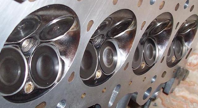
A modified VVA-Roller-version B16A2 1600cc Honda cylinder head. It has one Idle-Valve per cylinder.
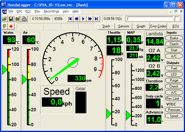
The idling recorded
with Hondata 's Logger
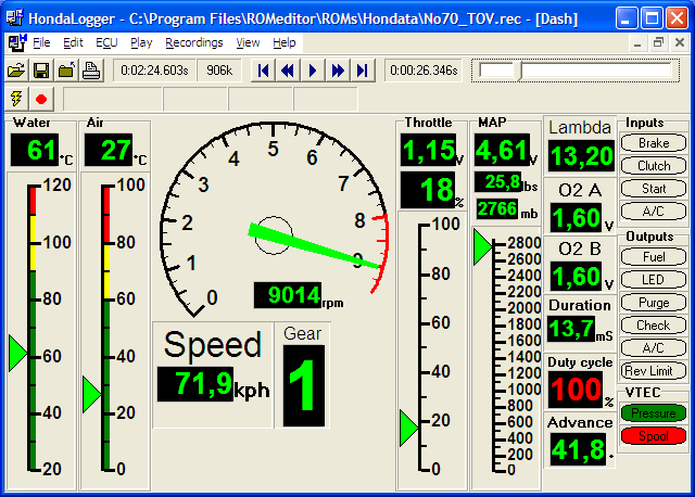
The same prototype
engine recorded at high revs
The problem lies
with the sensitivity of the breathing system at very short lifts: a slight
imbalance between the valve lifts (for instance due to uneven thermal expansion
or to uneven mechanical wear or to adjustment differences etc) causes an
intolerable uneven distribution of the charge among the cylinders. BMW's
valvetronic (a lost motion VVA) uses 0.3 mm intake valve lift for idling. BMW
manufactures the valvetronic parts with a 0.008 mm dimension accuracy. In
addition BMW moved to cross flow coolingto minimize the temperature differences along engine head. Pattakon's
B16A prototype (constant duration VVA) with 0.15mm intake valve lift idles at
300 rpm. The gap that restricts/controls the air flow to the cylinder at idling
is like a rectangle 200mm long (i.e. the periphery of the two intake valves) and
only 0.15mm wide (200/0.15=1330!). The quantity of the charge entering each
cylinder is roughly proportional to the lift of the valves of the
cylinder. If a 0.02mm tolerance is attainable for the intake valve lift, the
ratio (0.15+0.02)/(0.15-0.02) = 1.3 indicates that a cylinder can suction 30%
more charge than its neighbor cylinder! An idea of what the 0.02mm is: by
changing the temperature of the 102mm long intake valve for 17 degrees
centigrade, its length changes by 0.02 mm. The intake valve has to perform
quite different tasks: It has to combine high flow capacity, light weight and
robustness for top peak power at high revs, and, on the other hand, as soon as
the gas pedal is released it has to perform a strictly precise 0.15mm stroke to
allow the engine idle at 300 rpm.
Existing solutions: A way to face
the idling problem is to apply extreme construction accuracy, to use special
cooling system in order to minimize thermal differences along engine, to avoid
very slow idling revs (like 300 and 400 rpm), to avoid very high revs (like
7000, 8000, 9000 and more rpm), and live in the hope that the inevitable (on
long term) wear of the parts involved will be distributed equally to all
cylinders. Another solution is to use independent (i.e. per cylinder) VVA and
use feedback for continuous on-line adjustment. Another way is to use a
lambda sensor for each cylinder in order to control independently each injector
's duration, but in this case the uneven torque pulses will be noticeable.
Etc.
And an alternative way: Instead of fighting with the sensitivity
of the system at very short lifts, an alternative idea is to keep the normal
intake valves completely closed during idling and to feed the cylinders with air
or mixture through other intake valves (the idle-valves) of significantly lower
flow capacity.
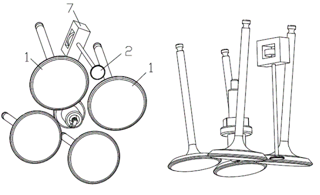
In practice: Starting with the B16A Pattakon 's
prototype, a hole of 7mm diameter, 25mm deep, is made beside each pair of intake
valves. Inside the hole a "bullet" like, one way ball valve (the idle-valve) is
nailed / bolted. The ball (from a ball bearing) inside the idle-valve is
3.2mm in diameter while the orifice is 2.5mm. With two short side holes (3mm
diameter) the input (i.e. the opening near the ball) of each idle-valve
communicates with the space above the heads of the two intake valves into the
intake port. The minimum intake valve lift is set to zero. Every time the gas
pedal is released, the two intake valves of each cylinder stay permanently
closed and the mixture is exclusively suctioned through the 2.5mm
orifice.
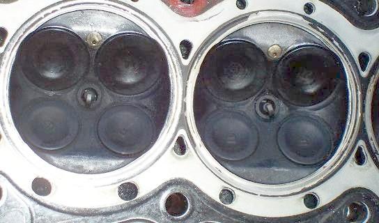
At idling the mixture enters into the cylinder through the 2.5mm
diameter orifice, while both 33mm diameter intake valves stay idle.
Comparing the size of the orifice to the size of the intake valves, the
problem is revealed.
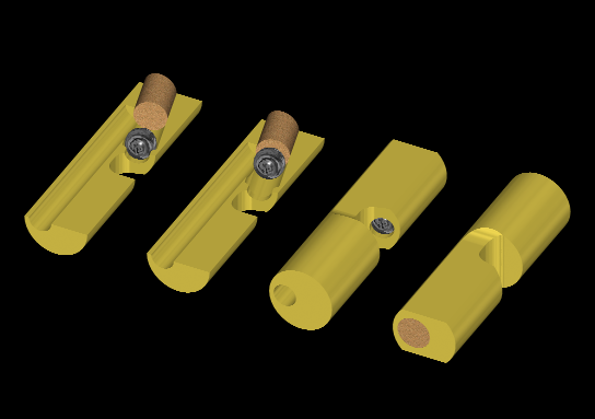
The idle-valve
schematically.
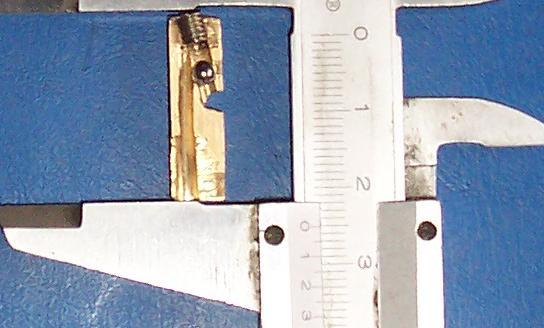
An idle-valve sliced,
the internals and the actual size (25mm long)<
When the pressure inside the cylinder is
lower than atmospheric, the ball is pushed upwards allowing mixture from the
intake port to enter the cylinder. As the piston moves upwards the pressure
inside the cylinder rises and comes a moment the one way valve closes. The rest
cycle continues as usual. At idling all intake valves stay permanently
closed, the charge flows into the cylinder exclusively through the 2.5mm hole
and the engine nicely idles at 330 rpm on stoichiometric mixture. Note that
at 330 rpm the kinetic energy stored into the rotating masses (flywheel,
crankshaft etc) is 5 times less than at 750 rpm of the conventional idling. Any
misfiring at 330 rpm would cause engine stalling. The transition from no load
(idling) to load operation is excellent. Under load the B16A prototype engine
behaves as before (i.e. without the idle-valves) providing top peak power at
12mm intake valve lift and 9000 rpm (where the rev limit is set) and flat torque
curve.
An interesting and useful result is that any time the gas pedal is
released, the intake control shaft returns to zero lift angle, leaving the
intake valves with their rocker arms and their rollers immovable, even if the
engine continues to rev high (for instance when braking with the engine). Note
that the prototype engine involves no spring other than valve
springs.
Fine tuning: A small adjusting screw is used as an obstacle
to the air flow from the intake port to the input of the idle-valve. Turning the
adjusting screw the resistance of the air path is changed. This way the charge
can equally be distributed to all cylinders. The adjustment resembles to the air
adjustment in old carburetors.
Applicability and variations: Any type
of VVA able to provide zero intake valve lift can be combined with the
idle-valves. Obviously the idle-valves are not necessarily one way valves
neither self lock valves. The location of the idle-valve is not restricted.
The size and weight of the idle-valves can become so small that they could
be formed even onto the heads of the intake valves.
In more sophisticated
applications the one way ball valve could be replaced by a small and light popet
valve of short stroke. This small popet valve could be controlled by a cam on
the camshaft. A better way to control a small popet idle-valve seems to be the
electromagnetic control: the idle-valve is much lighter than a normal valve, it
operates only at very low revs and performs a much shorter stroke. Controlling
the duration the idle-valve is kept open (a control similar to that used for the
fuel injection), the idling and even the light load operation at low revs could
be fully and accurately controlled.
Side
effects: The complexity added. The need for some modification of the
electric generator (or its pulley) to provide adequate voltage from 300 rpm to
keep the battery charged.
Idling Consumption: Procedure: The
power supply to the fuel pump is disconnected. The pipe from the fuel filter
to the injector 's collector is disconnected. A 2 liter transparent bottle is
used as fuel tank. A pre-weighted quantity of fuel is poured into the
bottle. Air is pressurized into the bottle at 2.2 bar. With a pipe from
the bottom of the bottle the injector 's collector is supplied with the
pressurized fuel. The injector table is modified to compensate the lower
fuel pressure.
At 330 rpm idling and stoichiometric mixture the fuel
consumption is 1 liter of unleaded regular gasoline per 3 hours (i.e. 11.5
hours/gallon or 340cc/hour or 250gr/hour, for this 1600 cc top power engine).
Tests with ethanol will follow.
Hybrid technology: Hybrid
technology takes advantage of the good efficiency of a conventional engine at
full load and medium revs to bypass / avoid the poor efficiency of the same
engine at low revs, high revs, partial loads and idling. If the efficiency
of the internal combustion engine were about constant at all revs and loads, the
hybrid technology would be useless. In hybrid cars the internal combustion
engine is not allowed to operate at partial loads and at idling. Despite the
inevitable energy loss during the transformation, storing and regeneration of
the kinetic energy, there is an overall gain in fuel economy proving the poor
efficiency of the conventional engine at specific operational conditions. On
the other hand an engine with VVA and idle-valves is characterised by more than
significant efficiency improvement at partial loads and at idling, leaving fewer
problems for the hybrid technology to deal with.
Conclusion The
ability of a VVA system to achieve tiny intake valve lifts is quite different
than the ability of the VVA to control precisely and on a long term basis the
idling operation. The problem is the sensitivity of the breathing system at
idling: the slightest difference between the intake valve lifts results in an
intolerable imbalance of the distribution of the gas among the cylinders. The
sensitivity problem is critical only for idling. Under the lightest
reasonable load the intake valve lift is several times higher than the idling
lift and therefore the sensitivity becomes several times lower than idling
sensitivity, making the normal accuracy and cooling adequate. With Pattakon
's idle-valves what is achieved is the liberation of the VVA system from the
idling operation. At idling the only duty left to the VVA is to leave the
normal intake valves closed. This, in turn, releases the design from extreme
construction accuracy, from special cooling system, from cost, from often
adjustments etc. As regards the quality and the efficiency of the idling
operation: the extreme velocity of the mixture entering the cylinder through
the small orifice of the idle-valve (improving mixture homogeny, charge
turbulence, flame propagation, operation stability), the significantly lower
pumping loss than conventional (no vacuum at intake port), the constant
geometry and dimensions of the idle-valves on a long term, and above all,
the idling fuel consumption in practice, is the answer.
Every engine
spends a percentage of its life at idling. In downtown traffic this percentage
increases, some times a lot. Every drop of fuel saved during idling is a
direct reduction of air pollution and a direct profit into owner's
pocket.
It would help the idling consumption data of any new car for
comparison.
The idling consumption has an advantage: it can be measured
with simple tools, any time, at any place and beyond any doubt. Please feel
free to ask for more details or for a demonstration.